 Log In
Search




 Open Access
 gengersgq@163.comOpen Accessgengersgq@163.com
To overcome the limitations of instruments in confined spaces, surgical robotics is considered a highly promising solution [9-11]. Commercialized laparoscopic surgical robots, such as the da Vinci SP system, demonstrate superior performance in larger cavities like the abdominal cavity through the introduction of wristed instruments [12-15]. However, their relatively large size makes them less suitable for minimally invasive procedures under strict spatial constraints. Consequently, research in this field has focused on highly flexible continuum robot designs [16-18].
Research efforts have explored various designs. For instance, a team from Incheon National University in South Korea developed a memory alloy-driven micro-flexible surgical robot [19]. Researchers at Shandong University developed a cable-driven surgical puncture robot, while Chinese scholars Luo et al. investigated a pneumatic/wire-driven continuum surgical robot for natural orifice surgery [20, 21]. A team from the Harbin Institute of Technology designed a magnetically driven millimeter-scale continuum robot for human lumen surgery [22]. A key challenge in the current research landscape is balancing the dexterity, size, stiffness, drive efficiency, and control complexity of such instruments. Practical devices specifically tailored for human body channels have yet to achieve significant breakthroughs. Among these diverse technical approaches, cable-driven systems are predominant in ultra-compact surgical instrument design due to their highly miniaturizable structure, immunity to electromagnetic interference, and ability to transmit power over long distances [23, 24]. However, many existing systems prioritize a high number of degrees of freedom, which often leads to excessive complexity without optimizing for core tasks such as planar tissue retraction in neuroendoscopic surgery. Building upon prior research, this paper introduces a specialized, compact, cable-driven manipulator specifically designed for planar tissue retraction in neuroendoscopic surgery. The Denavit–Hartenberg (D-H) parameter method and Monte Carlo simulations were employed to analyze the manipulator’s forward and inverse kinematics and its effective workspace, thereby validating the rationality and effectiveness of the overall design. Motion trajectory planning simulations conducted in MATLAB further verified the motion continuity of the manipulator.
2.1 Cable tension relationship analysis
To ensure stability and motion continuity, the manipulator employs an underactuated design [25]. This design features a minimalist joint topology consisting of three rotational joints arranged in a serial linkage configuration: a proximal finger pitch joint, a middle finger pitch joint, and an end-effector pitch/gripping joint (which provides tissue grasping/release functionality). The joint motion is constrained to a single plane, maximizing spatial efficiency. This approach addresses the critical requirement for surgical field exposure in neuroendoscopy while avoiding the complexity and spatial inefficiency associated with redundant degrees of freedom. All joint motions are actuated by a compact cable-driven system, ensuring a simple mechanical structure that can be integrated directly into the standard working channel of a neuroendoscope. Pitch motion is generated by winding cables around fixed pulleys located on both sides of each joint. Grasping and releasing functions of the gripping joint are operated by cables pulled through the central aperture of the joint. The cables are guided from the proximal end and routed counterclockwise over the fixed pulleys to drive the three joints. The gripping joint is secured by winding cables around its dissection aperture, as shown in Figure 1.

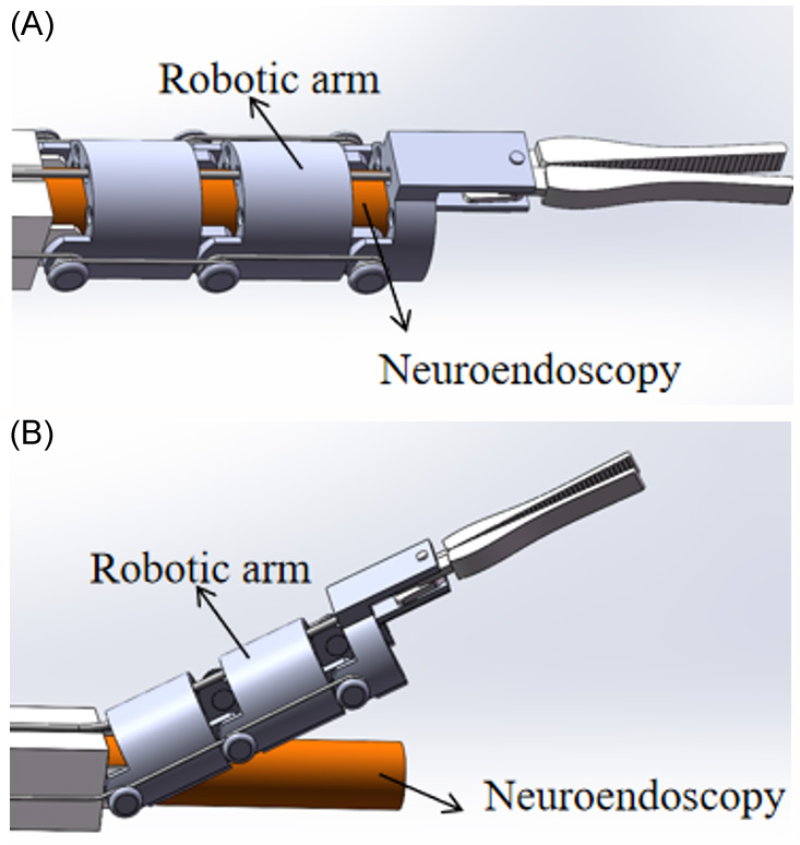
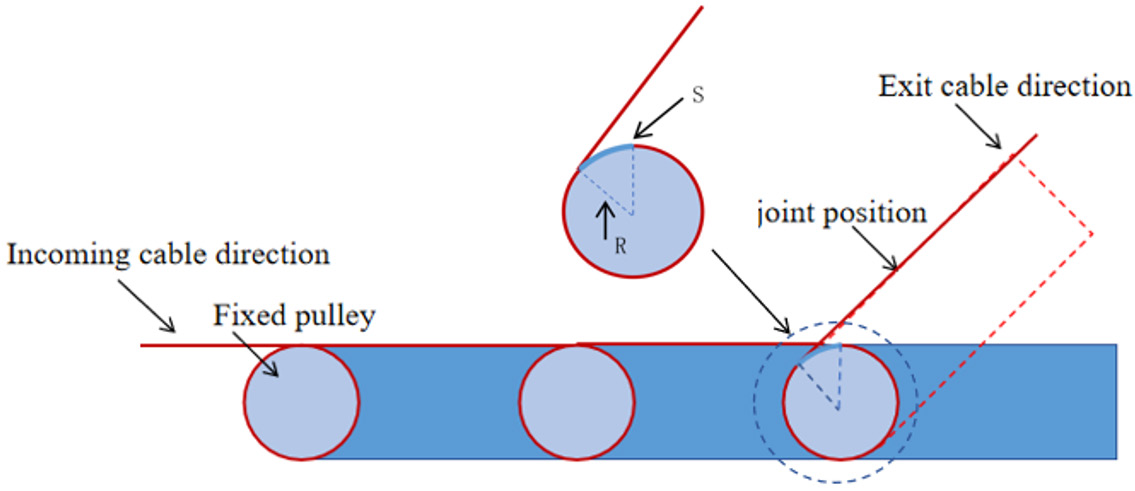
The rotation angle of each joint is determined by the length of cable being pulled. In the neutral position, the length of cable wrapped around each fixed pulley equals the pulley’s circumference. During rotation, the angular displacement corresponds to the arc length of the cable released, as shown in Figure 2. The relationship between joint angle and cable length is established through the following geometric derivation:

Applying the arc angle conversion formula yields:

Where θ₁ is the angle of arc displacement, S is the arc length, R is the radius of the fixed pulley, and θ₂ is the angle of the center circle.
Consequently, the relationship between the center circle angle and cable length variation is expressed as:

2.2 Maximum joint angle analysis
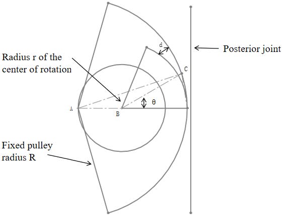
The maximum rotation angle θ for each joint is designed to be 30°, representing the ideal range of motion obtained through kinematic calculation. Due to an offset between the center of the arc at the joint end and the center of the fixed pulley, a specific clearance distance maintained between adjacent joints leads to a displacement during rotation. When this displacement equals the clearance at the rear joint, the two joints undergo rigid collision, halting rotation.
As shown in Figure 3, by constructing triangle ABC and applying trigonometric relations, the following is obtained:

Solving equation (4) yields:

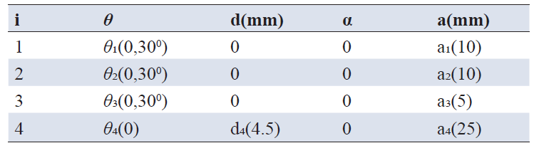
3.1 Forward kinematics
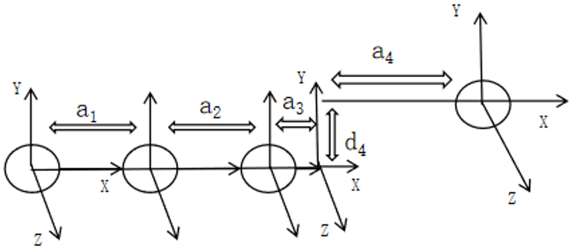
Forward kinematics provides the foundation for robotic motion control and path planning, involving the mathematical derivation of the end-effector pose from a given set of joint angles. It establishes the transformation between the robot’s base frame and the end-effector frame using a 4×4 homogeneous transformation matrix. This section presents forward and inverse kinematic analyses of the manipulator based on the established D-H parameter model [26]. The overall transformation matrix is obtained by successively multiplying the transformation matrices of individual joints.
The transformation matrix between adjacent robot links is defined as:

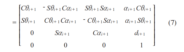
Where the following notation is used: cosθ=Cθ, sinθ=Sθ; cosα=Cα, sinα=Sα.
The joint rotation matrices, starting from the proximal joint, are as follows:
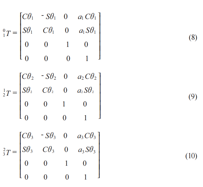
The final homogeneous transformation matrix defines the pose of the end-effector’s tip (gripping point) relative to the base frame:
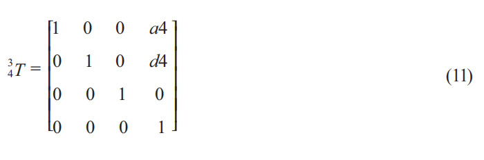
Denoting the homogeneous transformation matrix of the end-effector gripping point as:
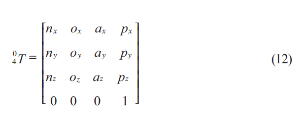
Based on the D-H method, overall transformation matrix for the end effector pose is obtained by concatenating the individual joint transformations:

The resulting elements of  are:
are:
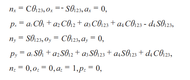
Where the abbreviated notation  is used.
3.2 Inverse kinematics
The inverse kinematics analysis determines the rotational angles θ of each joint based on the homogeneous transformation matrix of the robot’s end-effector joint pose, whose elements are given in Equation (12). This section uses the inverse transformation method to solve for the joint angles. The solution procedure is outlined as follows:
From Equation (13), we obtain:

Order:

Available:

Then the equation for θ2 is:

Rewriting Equation (15)-(16) as:

Squaring both sides of the equation and adding yields:

Define
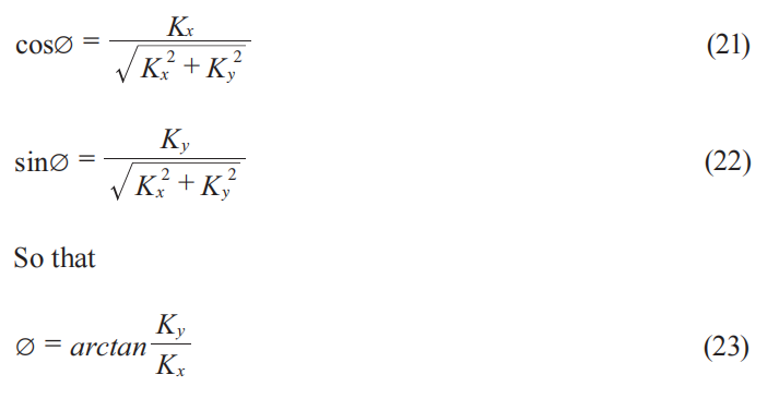
Using trigonometric relationships, the expression for θ₁ is:
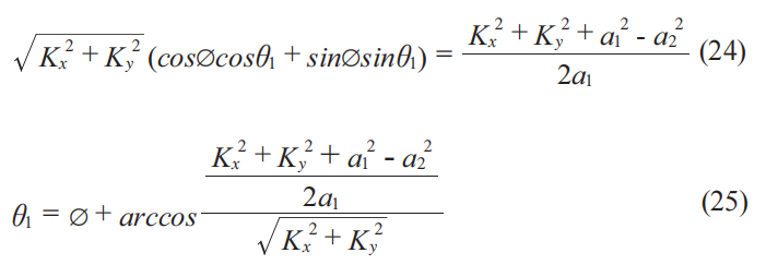
Then the equation for θ₃ is:

3.3 Static analysis
Based on the Lagrangian formulation for serial robotic arms, the dynamic equations of the finger mechanism are expressed as:

Where q=[θ1 θ2 θ3]T, denote the angular displacement, velocity, and acceleration vectors of the finger joints; D(q) is the inertia matrix; represents the centrifugal and Coriolis torque terms; G(q) is the gravitational torque; denotes joint friction torque; τt is the joint driving torque.
The elements of these matrices are calculated based on the geometric and inertial parameters of the three links. Substituting these elements into Equation (27) yields the complete dynamic equations of the finger mechanism.
The three finger segments are denoted as link 1, link 2, and link 3, with masses m₁, m₂, m₃, and moments of inertia about their respective centers of mass.
The Lagrange method is employed to solve for the joint torques. The fundamental expression of the Lagrange equation is:

In the equation, L represents the Lagrangian operator, where L=K-P, with K the total kinetic energy and P the total potential energy of the linkage system. To proceed, the linear velocities, accelerations, and angular accelerations of each link must be determined individually. Substituting the Lagrangian into equation (27) and performing differential calculations yields the corresponding torque matrix.
For link 1, the position of its center of mass in the coordinate system O1 X1Y1Z1 can be represented as 1pr1=[r1,0,0]T.
Rotating about the origin of the basis coordinate system with angular velocity , its linear velocity is .
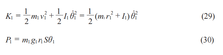
The kinetic and potential energies of link 1 are respectively:
For rod 2, its center of mass in the coordinate system O2 X2Y2Z2 can be expressed as .
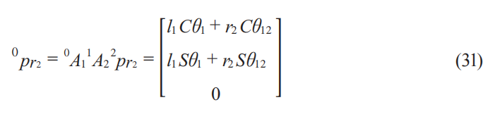
Through coordinate transformation, its position 0pr2 in the base coordinate system can be expressed as:
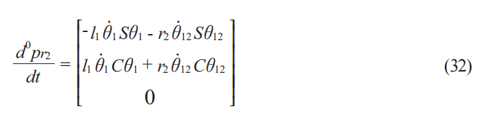
According to equation (31), the absolute velocity of the center of mass of rod 2 can be calculated as:
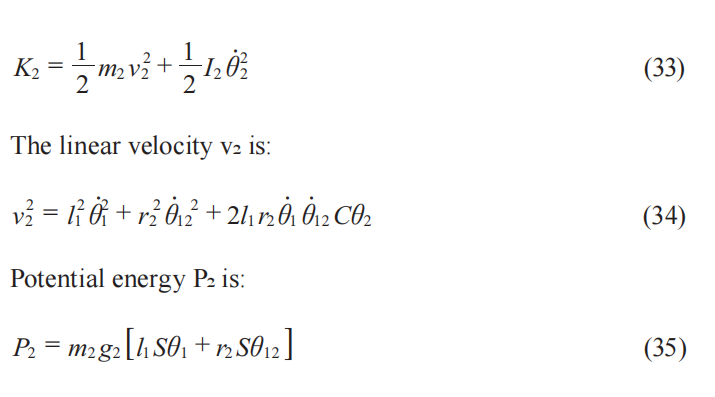
Accordingly, the kinetic energy K2 of rod 2 can be determined as:
For rod 3, its center of mass in the coordinate system O3-X3Y3Z3 can be expressed as 3pr3=[r3,h3,0]T.
Through coordinate transformation, its position 0pr2 in the base coordinate system can be expressed as:
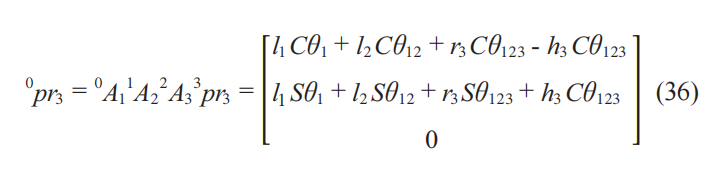
According to equation (36), the absolute velocity of the center of mass of rod 2 can be calculated as:
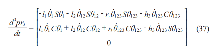
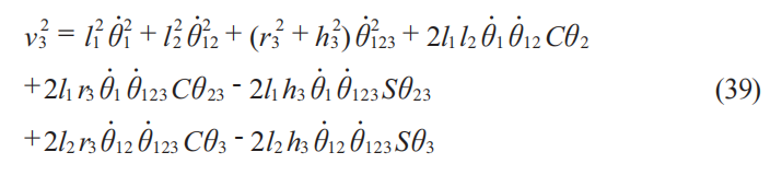
Accordingly, the kinetic energy K3 of rod 3 can be determined as:

The linear velocity v3 is:
Potential energy P3 is:

Both the kinetic energy and potential energy of the linkage system have been determined, enabling the calculation of the Lagrangian operator:

Using the Lagrange operator L, calculate the partial derivatives for each joint variable: 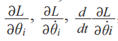 , i=1,2,3. Substituting the above results into the Lagrange equations (27) yields the joint torques.
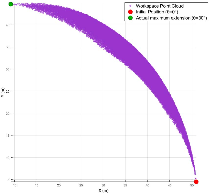
The workspace of the manipulator was analyzed using the Monte Carlo method [27]. A large number of random joint angle combinations were generated within their allowable ranges, and the corresponding end-effector positions were computed via the forward kinematics model in MATLAB. The point cloud representing these positions was plotted to visualize the workspace. As shown in Figure 5, the robotic arm’s motion range forms a crescent shape, with spatial extents of X∈(10, 50.9) mm and Y∈(5.3, 44.9) mm. This extensive motion range meets the practical movement requirements of each mechanical joint and effectively fulfills the design task of expanded traction.
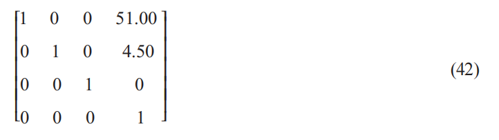
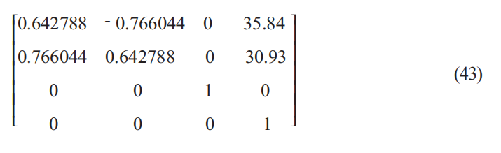
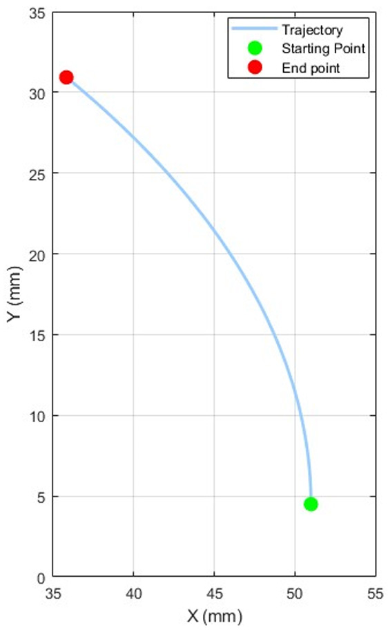
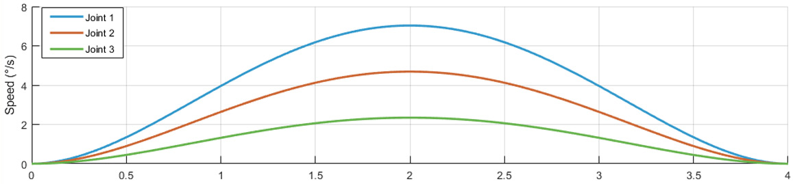
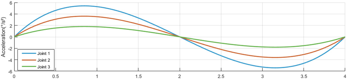
Trajectory planning is a critical aspect of robotics, as it significantly influences the performance and smoothness of robotic motion. In this study, a point-to-point trajectory between specified initial and terminal poses was planned. The trajectory was generated using quintic polynomial interpolation via the MATLAB Robotics Toolbox, based on the established kinematic model. This process generated the angle, angular velocity, and angular acceleration profiles for the three joints along the planned path.
Starting pose:
Terminal pose:
The resulting trajectories are shown in Figure 6.
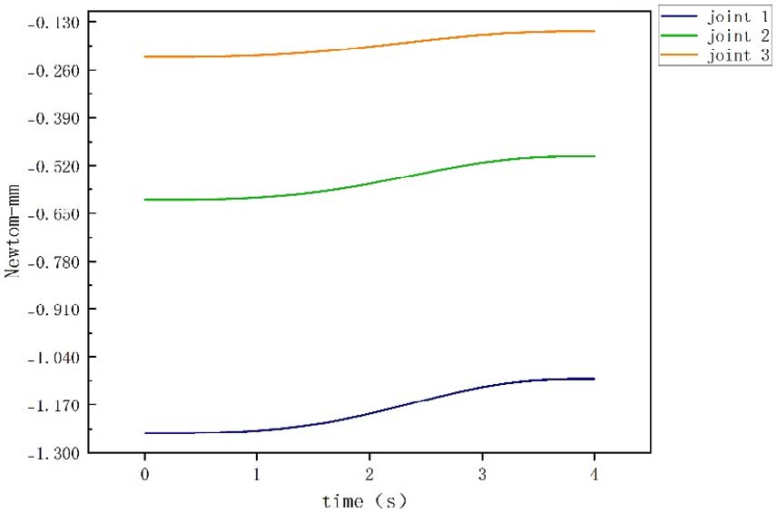
As illustrated in Figures 7-9, the angular displacement, velocity, and acceleration profiles of all three joints demonstrate smooth transitions without abrupt changes during motion along the planned trajectory. This finding indicates that all joints can be driven stably throughout the workspace, thereby validating the rationality of the mechanical design. The manipulator model developed in SOLIDWORKS was subsequently imported into ADAMS for dynamic simulation. Within the ADAMS environment, the material properties were defined as steel, and the corresponding joint torque profiles were acquired. Collectively, these simulation results provide an intuitive and practical reference for the subsequent development of the physical platform and the design of its control system.

As shown in Figure 10, the negative values on the Y-axis indicate only the direction of the torque, not its magnitude. The torque variation curve reveals that the torque at all three joints exhibits an approximately S-shaped continuous trend. The transitions are smooth and uniform, with no abrupt changes observed. This indicates that the load transition at each joint during motion is stable, meeting the design expectations and stability requirements.
This study addresses the practical need for tissue retraction in neuroendoscopic surgery by presenting the design of a compact, cable-driven manipulator tailored for minimally invasive procedures. The proposed manipulator employs an underactuated design with a minimalist three-joint topology, achieving stable planar motion. This configuration significantly reduces the spatial footprint while ensuring full functionality, thereby enabling seamless integration into standard neuroendoscopic working channels. This makes the manipulator particularly suitable for confined surgical environments.
In terms of mechanism design, the maximum joint rotation angle was mechanically constrained through the coordinated design of joint arcs and fixed pulleys, coupled with precise clearance control. A kinematic model was established based on the D-H parameter method, and the forward and inverse kinematic relationships were systematically derived. Furthermore, a static model was constructed using the Lagrange method, providing a theoretical foundation for control and force feedback. Trajectory planning analysis conducted in MATLAB demonstrated that the manipulator possesses a feasible crescent-shaped workspace, which is sufficient for the required traction and exposure of surgical sites. The combined results from the trajectory and torque simulations revealed continuous and smooth motion profiles for all joints, with no abrupt changes, further validating the rationality of the mechanism design and its motion stability.
While this study has made significant progress in structural design and kinematic analysis, several limitations remain to be addressed. For instance, the current model does not incorporate effects such as time delay and deformation caused by cable flexibility. Furthermore, the mechanical performance under extreme loading conditions requires further experimental validation. Future work also includes coordinating the manipulator’s motion with a robotic arm to achieve free movement in three-dimensional space, which warrants further investigation.
Author contributions
Both authors contributed equally to the work. Liu participated in the implementation and drafting of the manuscript, while Shi contributed to the conceptual development and design of the study.
Funding
This research received no external funding.
Data availability
The data presented in this study are authentic and reliable.
Ethics approval and consent to participate
Not applicable (this study did not involve any procedures requiring ethical review).
Consent for publication
The submitted manuscript has not been published elsewhere (except in the form of an abstract or a conference presentation) and is not currently under consideration for publication by any other journal.
Competing interests
The authors declare no potential conflicts of interest with respect to the research, authorship, or publication of this article.
Acknowledgements
Not applicable.
ISSN: 2957-5478
Volume 4, Issue 1
March 2026
Pages: 1-76


 Log In

 On This Page
 CITE
CITE